Understanding SFP+ Transceiver Testing
In the 10 Gigabit Ethernet world, fiber optical transceivers have been developed along the way to meet the increasing usage and demand for higher-performance servers, storage and interconnects. The small form-factor pluggable plus (SFP+) can be referred to as an enhanced version of the SFP that supports data rates up to 16 Gbit/s. SFP+ supports 8Gbit/s Fiber Channel, 10 Gigabit Ethernet and Optical Transport Network standard OTU2. It is a popular industry format supported by many network component vendors. In order to ensure the high performance of the SFP+ transceivers, one critical point is to deal with the testing issues of them. This article will first illustrate the SFP+ testing challenges in reality and then focus on one important testing measurement.
The most obvious challenge is the increased port density and the testing time required with 48 or more ports per rack. For instance, there are 15 measurements each for the host transmitter tests, and each of those measurements using manual methods will take about three to five minutes. This means a test engineer will take more than an hour per port to finish the required tests, multiplied across the number of ports.
Another challenge is moving seamlessly from a compliance environment to a debug environment. If a measurement fails, how can the designer decide which component causes the failure and debug the issue to arrive at the root cause?
Next, most designers may confront with today relates to connectivity: how to get the signal out from the device under test (DUT) to an oscilloscope. Test fixtures are typically required but questions arise around whether the fixtures have been tested and validated against the specification.
Another challenge to prepare for is that the SFP+ specification calls out some measurements to be performed using a PRBS31 signal. Some measurements have PRBS31 as a recommended pattern. The maximum record length possible for acquisition with popular high-performance real-time oscilloscopes is 200 million samples. At a sampling rate of 50 Gsamples/s, the designer can acquire around 40 million unit intervals (UIs). At a sampling rate of 100 Gsamples/s, the instrument can acquire 20 million UIs. However, a PRBS31 pattern has more than 2 billion UIs. Thus, acquiring an entire pattern presents a challenge.
What’s more, acquiring a record length of 200 million data points demands huge processing power and time. One solution is to treat the PRBS31 waveform as an arbitrary waveform and acquire a modest record length of 2 million to 10 million UIs to recover the clock and compute the results. This provides a good tradeoff between processing power and test-result accuracy.
TWDPc, short for transmitter waveform distortion penalty for copper, requires a special algorithm defined by the SFP+ specification. This test is defined as a measure of the deterministic dispersion penalty due to a particular transmitter with reference to the emulated multimode fibers and a well-characterized receiver.
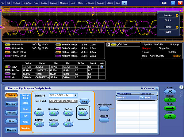
The TWDPc script (of 802.3aq, 10GBASE-LRM) processes a PRBS9 pattern requiring at least 16 samples per unit interval. Out of concern for the large installed base of equivalent-time oscilloscopes with a record length of around 4000 samples, the requirement for 16 samples per unit interval was relaxed to seven samples per unit interval.
The relaxation of the requirement from 16 samples per unit interval to just seven samples per unit interval causes worst-case pessimism of 0.24 dB TWDPc over 30 measurements. For DUTs that already have a high TWDPc, 0.24 dB can be the difference between a pass or a fail result.
The TWDPc measurement for SFP+ host transmitter output specifications for copper requires more than 70 Gsamples/s to capture a minimum of seven samples per UI. Real-time oscilloscopes offering higher sampling rates of 100 Gsamples/s or greater have a much higher chance of providing accurate results for TWDPc compared to scopes that only offer lower sampling-rate options.
Across the board, it is important to map the SFP+ signal’s data-transfer rate to the proper oscilloscope bandwidth requirements to ensure accuracy in measurement and margin testing. With a 10.3125-Gbyte/s data-transfer rate and minimum rise time of 34 ps, a scope with a bandwidth of 16 GHz or higher is required to meet the minimum requirements for SFP+. As noted, sampling rate is also an important consideration for the TWDPc measurement.
To overcome SFP+ transceiver testing challenges, fiber optical equipment manufacturers have developed solutions that can run through all SFP+ measurements quickly, generate reports, and allow access to a debug mode if the testing requires it. But in order to assure the high performance of the whole system, choosing reliable and cost-effective SFP+ modules is equally important. FS.COM offers a wide range of SFP+ transceivers, like SFP-10G-SR-X, SFP-10G-ER, SFP-10G-LRM, etc. Each fiber optic transceiver has been tested to ensure the customers to receive optics with superior quality.